
MichiganMightyMite
Michigan Mighty Mite QRP CW (Morse Code) Transmitter
Section titled “Michigan Mighty Mite QRP CW (Morse Code) Transmitter”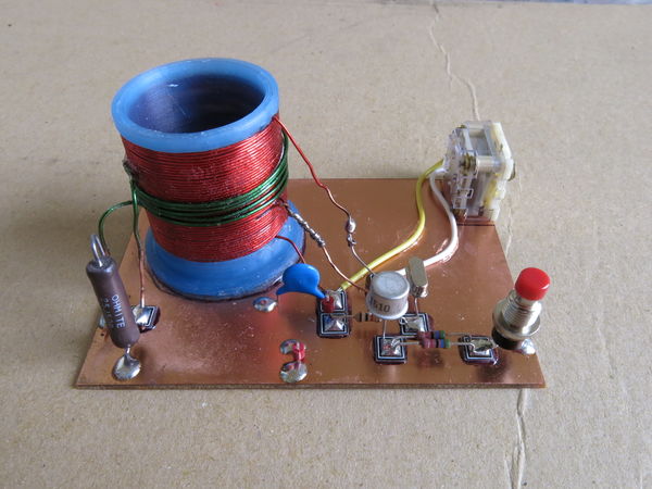
80m Morse Code Transmitter
Dallas Makerspace
Amateur Radio Special Interest Group
Build class
The Rules
Section titled “The Rules”If you build the transmitter according to the directions provided here, you will be in compliance with FCC rules concerning experimental radio transmitters, even if you do not have an Amateur Radio license. If your interested in modifying the transmitter we produce in this class, and you have an Amateur Radio license, basic guidelines to do so will be included in an appendix. You can also contact myself or other members of the Amateur Radio special interest group to help you in testing your modified transmitter to ensure it complies with FCC regulations.
Basic description of circuit
Section titled “Basic description of circuit”This transmitter is a basic Pierce crystal oscillator. The combination of the T1 primary and capacitor C1 form what is known as an LC (inductor-capacitor) tank circuit with a tuned frequency that matches the oscillation of the crystal provided. This crystal’s oscillations have an amplified feedback through the base and collector (through the LC tank circuits connection to this junction). The momentary contact switch turns the oscillator on, by completing the circuit with ground. The continuous wave (CW) oscillations are fed into the primary of T1, through a tap that matches the impedance of the primary to the collector of the transistor. The oscillations (AC electrical power) induce a similar AC voltage at the output of the transformer. This signal is then fed to two 100 ohm resistors in parallel to form what is called a 50 ohm dummy load. This dummy load simulates the inductance expected from an antenna. By using this dummy load we minimize the radio frequency (RF) power radiated by the circuit. This prevents the transmitter for causing undue interference; however, there is still enough radiated RF so that the signal can be picked up from a nearby radio receiver.
Schematic and Circuit Layout Diagrams
Section titled “Schematic and Circuit Layout Diagrams”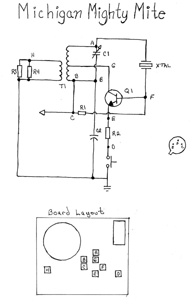
Assembly Instructions
Section titled “Assembly Instructions”1. Bare board and parts
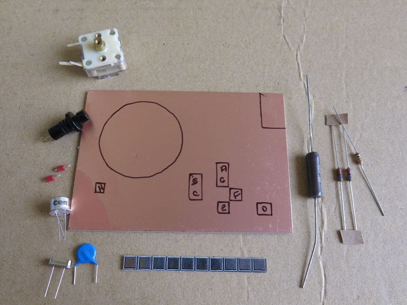
2. MePADS and Cap glued in place
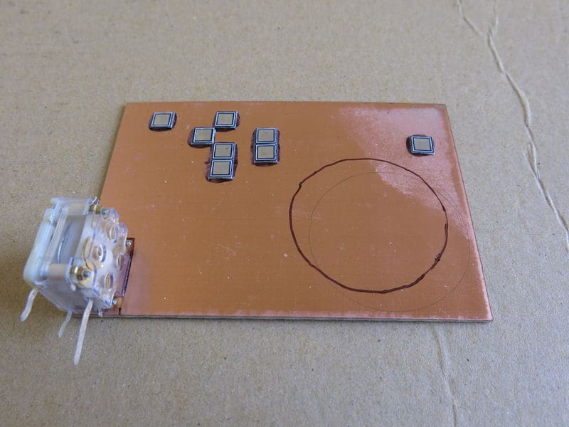
3. R1, 10k resistor installed
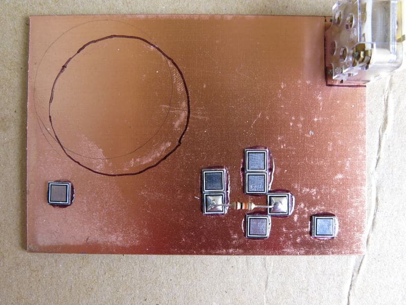
4. Q1, transistor installed
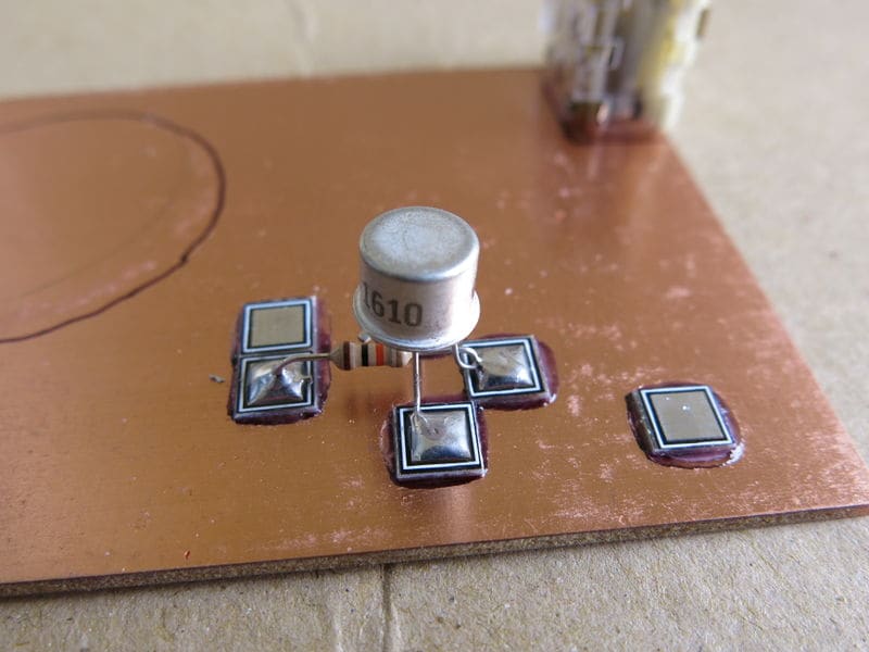
5. Install tie points for power and ground
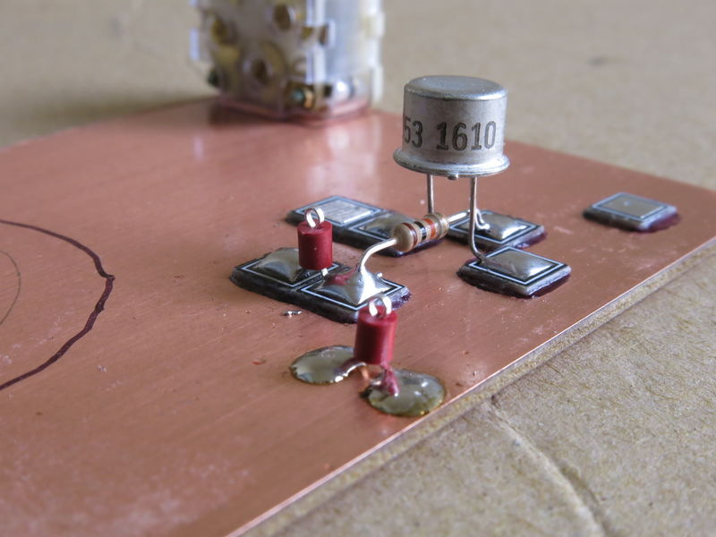
6. Solder R2 between E & D (2 53 ohm resistors)
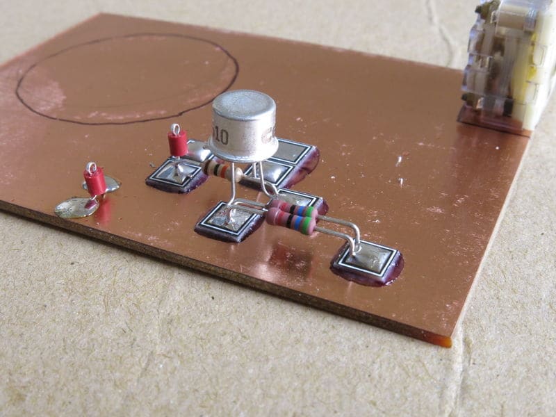
7. Solder XTAL1, (crystal) to A & F
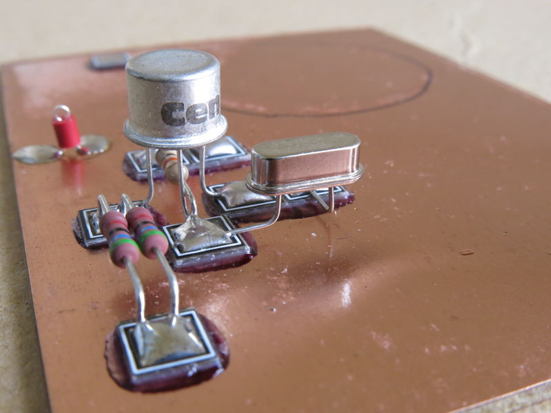
8. Solder C2 (blue capacitor) between B & ground plane
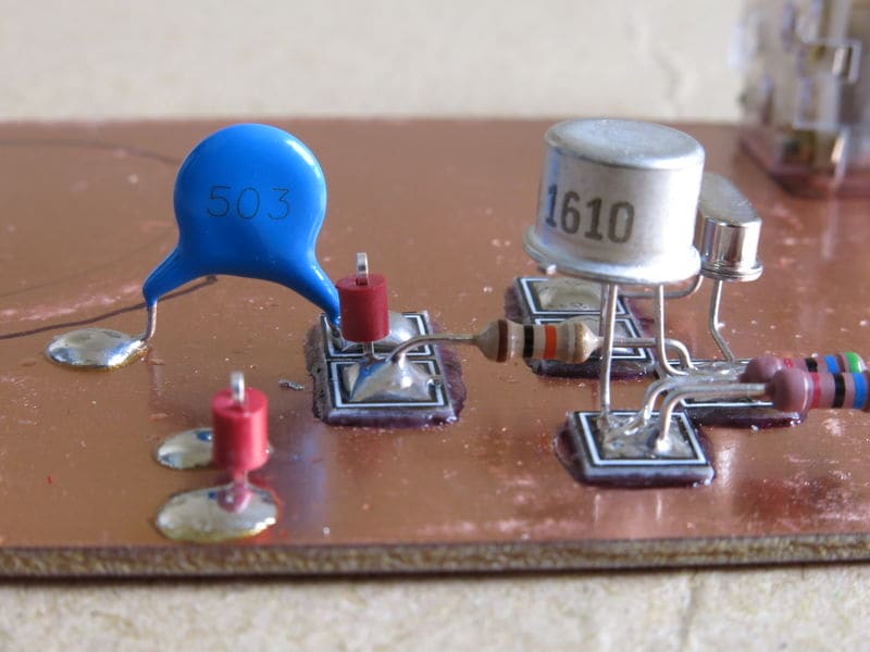
9. Install R3&R4 (large resistor replaces R3&R4) between H & ground plane
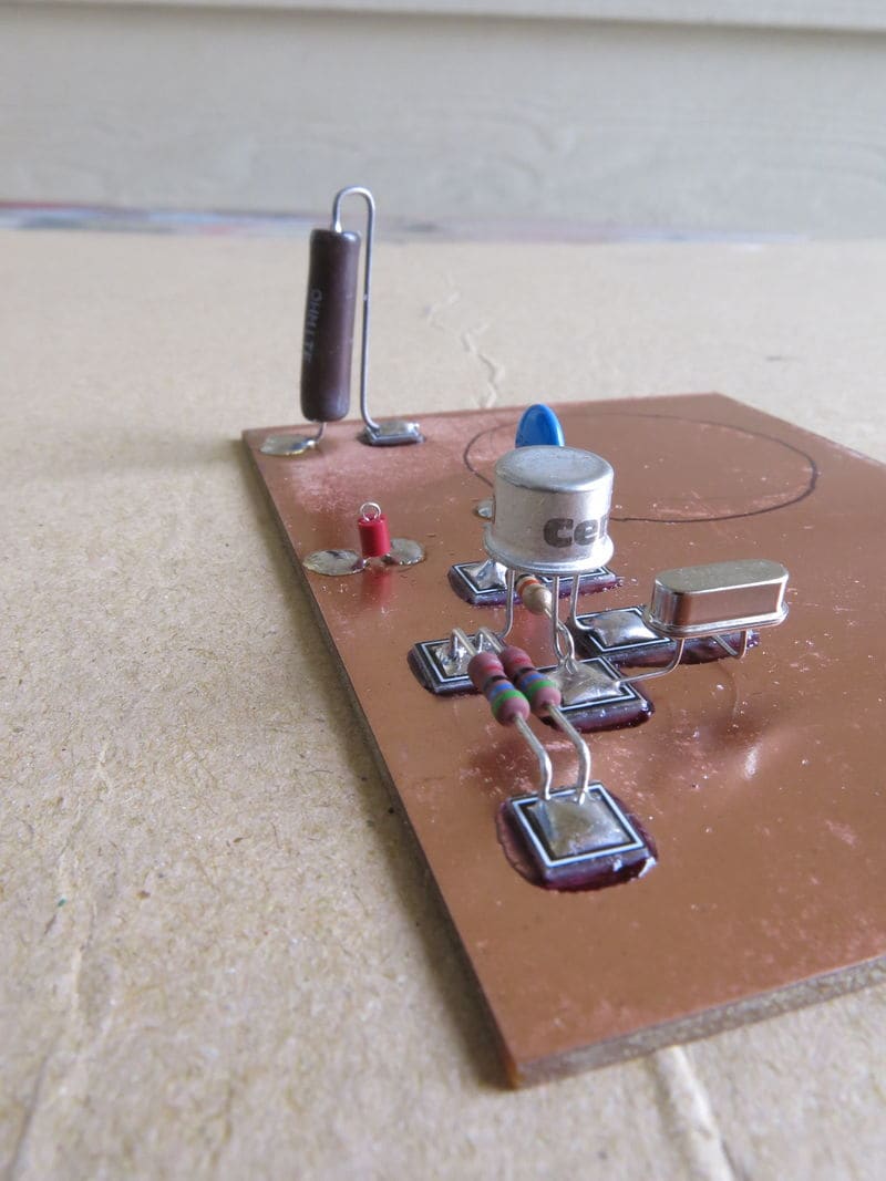
10. Install switch between D & ground plane
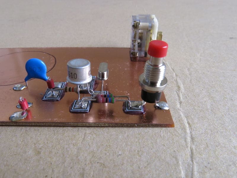
11. Use wire to connect two front connectors on variable capacitor to A
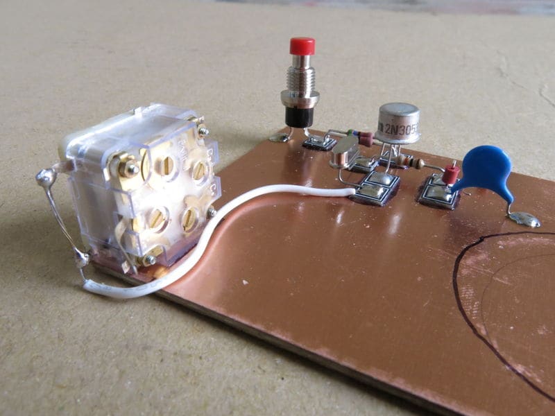
12. Use wire to connect rear connector on variable capaitor to B
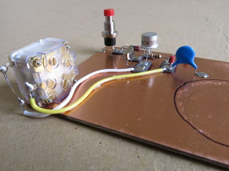
13. Apply glue to copper, just inside the circle marked on the board
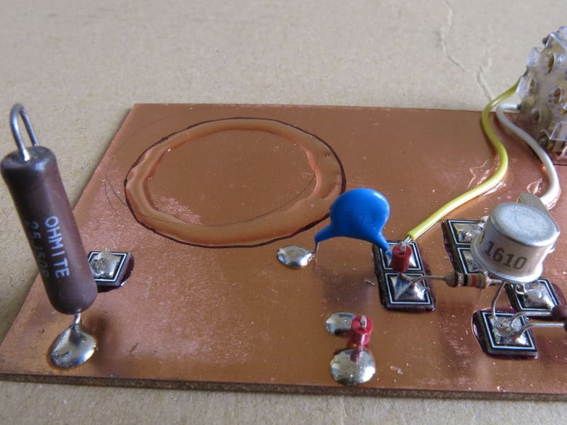
14. Glue coil form in place
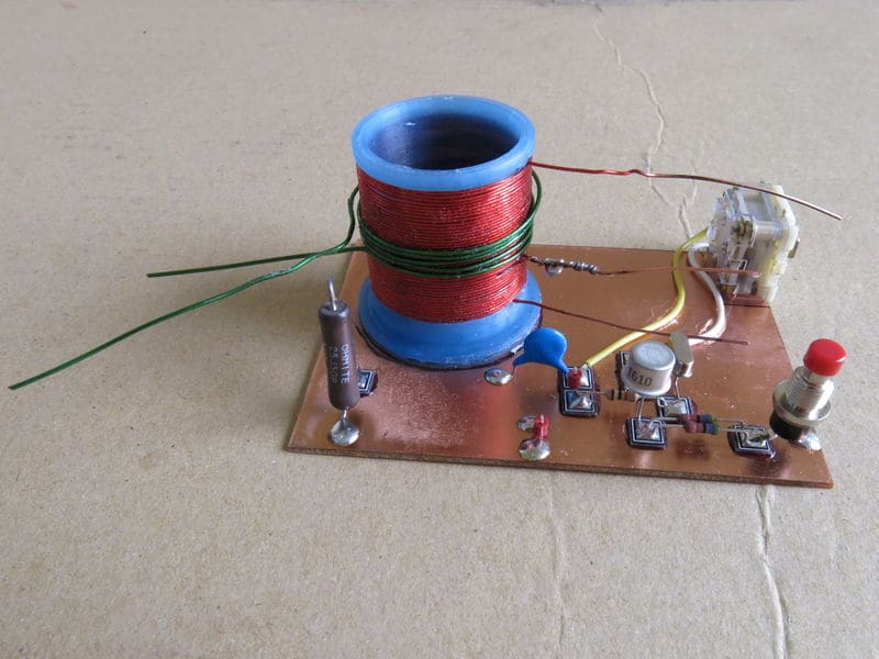
15. Solder the bottom of the secondary coil to the ground plane and the top of the secondary to H
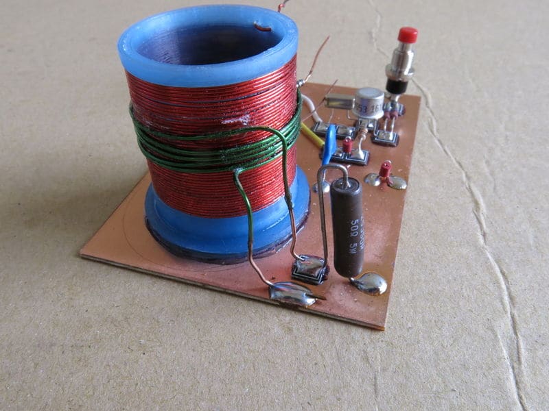
16. Solder the lower primary coil to B
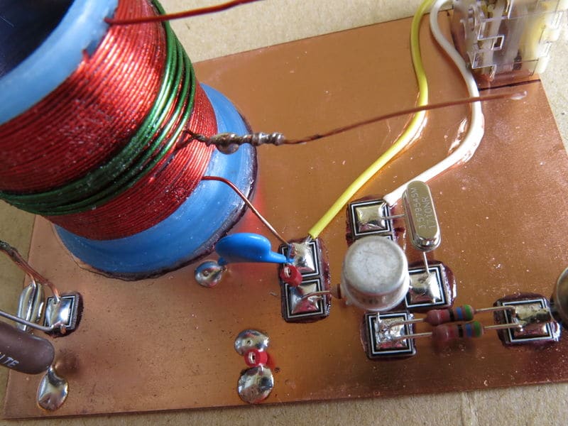
17. Solder the middle connection of the primary coil to G
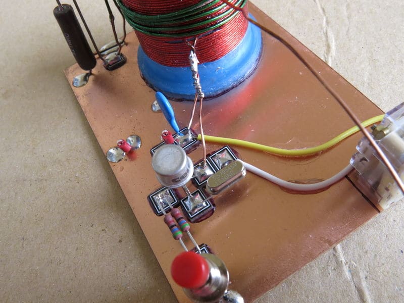
18. Solder the top of the primary coil to A
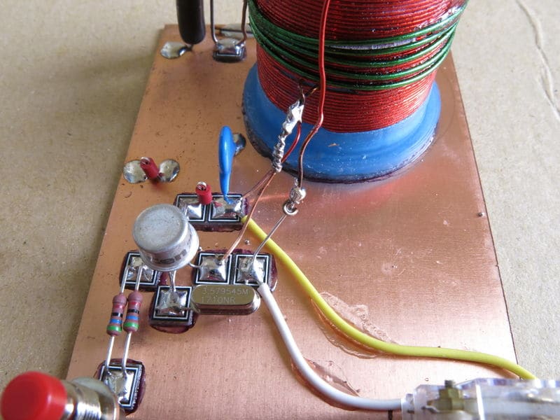
Parts List (80m Version) with links to sources for each part
Section titled “Parts List (80m Version) with links to sources for each part”| Code | Description |
|---|---|
| C1 | 2 x 265 pF Polyvaricon capacitor, wired in parallel |
| C2 | 0.05uF Capacitor |
| R1 | 10k ohm, 1/4 watt, 5% resistor |
| R2 | 27 ohm, 2W, 5% resistor |
| R3, R4 | 100 ohm, 2W, 5% resistor |
| S1 | Momentary pushbutton switch |
| T1 | Primary, 45 turns, tapped at 15 turns; Secondary 6 turns. Use 22 awg enameled wire on 1 1/4" diameter form (33mm film canister) |
| Q1 | 2N3053 NPN Transistor |
| XTAL | 3.579MHz (HC49) Crystal |
| Coil form | Thingiverse files |
| Miscellaneous | Single sided PC board (FR4) about 70mm x 100mm x 1.5mm, 8 MeSquares or other small pieces of PC board, 22 gauge enameled wire (16 feet for primary and 3 feet for secondary, hook-up wire, super glue, solder |
Low pass filter (by band)
Section titled “Low pass filter (by band)”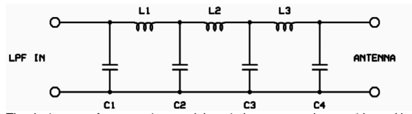
| Band | C1 | C2 | C3 | C4 | L1/L3 | L2 | Toroid |
| 160 | 820pF | 2200pF | 2200pF | 820pF | 30T (4.44uH) | 34T (5.61uH) | T50-2 (red) |
| 80 | 470pF | 1200pF | 1200pF | 470pF | 25T (2.42uH) | 27T (3.01uH) | T37-2 (red) |
| 40 | 270pF | 680pF | 680pF | 270pF | 21T (1.38uH) | 24T (1.70uH) | T37-6 (yellow) |
| 30 | 270pF | 560pF | 560pF | 270pF | 19T (1.09uH) | 20T (1.26uH) | T37-6 (yellow) |
Additional Reference Material
Section titled “Additional Reference Material”- Excellent introduction to building circuits with the Manhattan Circuit building technique
- W2AEW Builds the mighty mite
- Mighty simple shortwave transmitter
- Hack-a-day minimal mighty mite
- So you want to be a shortwave pirate broadcaster? — Describes how to modify mighty mite circuit to transmit AM voice
Migrated from the legacy DMS wiki: original page